Masters
Mies van der Rohe: Tugendhat house, Brno, 1928-30
Mies van der Rohe in June 1929 starts to oversee the construction of Tugendhat House, just a month before he had concluded the realization of the German Pavilion in Barcelona. The design of these two buildings runs parallel, the Barcelona pavilion indeed anticipates some solutions that Mies will have the time to develop more thoroughly in Brno.
In these two buildings Mies shows for the first time the metal structure, which until then had always been embedded in thick masonry walls. The idea of exposing the metal structure coincides with the discovery of the column as an architectural element able to dynamically impact the building space.
The column is a cruciform pillar obtained by joining and bolting together four L profiles, adding one or two metal shimming plates. The column does not present entasis, base or capital, it does not terminate with a lintel. The Barcelona column expresses the way it has been assembled and it adheres to its core; the column in Brno is a polylobated wrapping, a metallic tunic which has a reflective chrome surface.
The building in Brno is formed by a metal structure with a 490 x 550 cm grid, cruciform pillars of the same building height and profiled floor beams bolted to the pillars. The building slab is made of load-bearing concrete brick beams and ceiling bricks while the walls are masonry with cement plaster. String courses, parapets of the terraces and skirt-boardes are in travertine. The window frames are in metal and on the first floor there is one large full height glass window both on the south and east side. To the south the two central bays have big windows that can be lowered to the floor.
The chrome plated columns fit into the space not as part of a three-dimensional structural frame, but as isolated elements emphasizing their plastic character. The concept to decorate a domestic space with structural steel elements may have been developed by Mies during his experience at the Werkbund in Stuttgart where Mart Stam and Hans Scharoun made this choice for the first time.
Marko Pogacnik, IUAV University Venice
with Andrea Ambroso.
The research was made possible thanks to the collaboration of the colleagues: prof. Wolf Tegethoff, dr. Rudolf Fischer, arch. Ivan Wahla, arch. Jan Sapak, dr. Miroslav Ambroz, Paul Galloway.
Read text
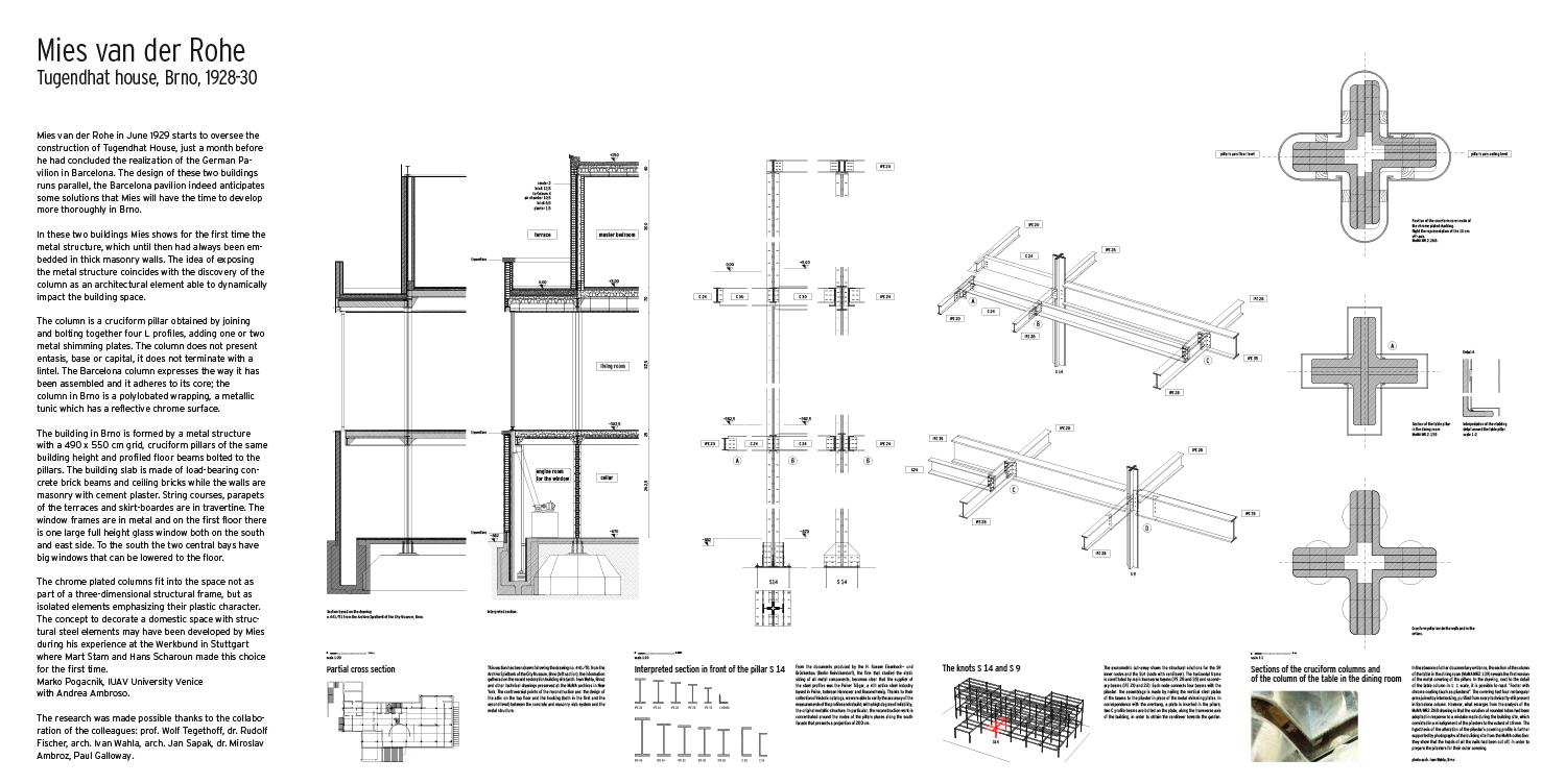
1 – Partial cross section, 1: 20
This section has been drawn following the drawing no. 441/51 from the Archive Spielberk of the City Museum, Brno (left section), the information gathered on the recent restoration building site (arch. Ivan Wahla, Brno) and other technical drawings preserved at the MoMA archives in New York. The controversial points of the reconstruction are: the design of the attic on the top floor and the hooking (both in the first and the second level) between the concrete and masonry slab system and the metal structure.
2 – Partial cross section of the pillar S16, 1: 10
From the documents produced by the H. Gossen Eisenhoch- und Brückenbau (Berlin Reinickendorf¬¬¬), the firm that studied the static sizing of all metal components, becomes clear that the supplier of the steel profiles was the Peiner Träger, a still active steel industry based in Peine, between Hannover and Braunschweig. Thanks to their collection of historic catalogs, we were able to verify the accuracy of the measurements of the profiles and rebuild, with a high degree of reliability, the original metallic structure. In particular, the reconstruction work is concentrated around the nodes of the pillars places along the south facade that presents a projection of 200 cm.
3 – The nodes S 11 and S 16, 1: 20
The axonometric cut-away shows the structural solutions for the S11 inner nodes and the S16 (node with cantilever). The horizontal frame is constituted by main transverse beams (IPE 28 and 40) and secondary beams (IPE 20 and 22). Each node connects four beams with the pilaster: the assemblage is made by nailing the vertical steel plates of the beams to the pilaster in place of the metal shimming plates. In correspondence with the overhang, a plate is inserted in the pillars; two C profile beams are bolted on the plate, along the transverse axis of the building, in order to obtain the cantilever towards the garden.
4 – Sections of the cruciform column and (center) of the column of the table in the dining room, scale 1: 1
In the absence of other documentary evidence, the section of the column of the table in the dining room (MoMA MR2.139) reveals the first version of the metal covering of the pillars. In the drawing, next to the detail of the table column in 1: 1 scale, it is possible to read: “Footer with chrome coating (such as pilasters)”. The covering had four rectangular arms joined by interlocking, purified from every technicality still present in Barcelona column. However, what emerges from the analysis of the MoMA MR2.268 drawing is that the solution of rounded lobes had been adopted in response to a mistake made during the building site, which consisted in a misalignment of the pilasters to the extent of 18 mm. The hypothesis of the alteration of the pilaster’s covering profile is further supported by photographs of the building site from the MoMA collection: they show that the heads of all the nails had been cut off, in order to prepare the pilasters for their outer covering.